-40%
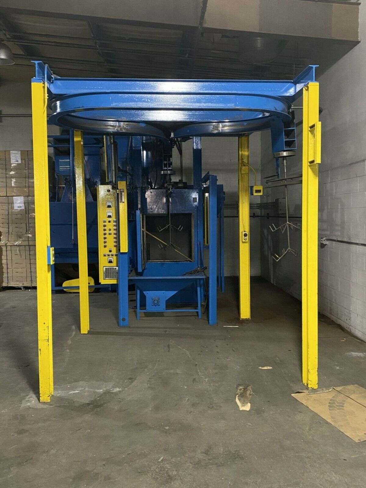
Bronco Spinner Hanger Sandblasting Machine Blast Cleaning Shotblast 1-3 Station
$ 36432
- Description
- Size Guide
Description
Bronco shot blast equipment is used to clean metal castings, heat treated parts, structural steel, fabrications and forgings. Typical applications include deflashing, descaling, paint and rust removal and preparation for coating adhesion. This system is used for die casting operations. The Y-track on this 1-3 Station Spinner system is robust and typically used for larger castings. Variable Speed 1,000-3,500 RPM, Auto Time and Manual, Transfer, Inside Lining was Re-Done, Ran 30-50 hours, 30/30 Control with Variable Speed Wheels 480-Volts. This older system is in excellent condition with robust construction. Specifications of this system follow:CABINET
3/8.,
R.P.Q.,
500
Brinnel
through
hardness.
Ceiling
and
the
wall opposite
the
blast
wheels
have
3/8"
R.P.Q.
500
liners.
DOORS
Two
doors
hinged
on
each
side
of
the
cabinet
with
a
1-7/16"
dia. shaft,
riding
in
1-7/16"
dia.
Dodge
"SC"
pillow
block
bearings. A
4"
wide
overlap
bar
on
the
right
hand
door
prevents
leaking when
the
doors
are
closed.
The doors are opened and closed by means
of
a
3"
bore,
10"
stroke
air
cylinder
connected
to
each door
shaft.
The right hand door comes full open and then the left hand
door
opens.
The
opposite
happens
when
they
close.
An
air
inlet
hopper
below
the
doors
will
catch
any
falling
media when
they
open.
The
wheels
will
not
run
when
the
doors
are
open. The doors will not open if the media is
on.
HELICOIDS
Two
6"
dia.
helicoids
convey
the
spent
media
from
the
twin
gravity hoppers
in
the
floor
of
the
cabinet
to
the
elevator
boot.
Above the
helicoids
there
is
a
wire
floor
to
prevent
any
large
foreign material
from
entering
the
abrasive
reclaim
system.
The
helicoids
are
driven
by
chain
and
sprocket
from
the
boot
shaft
of
the
elevator.
ELEVATOR
1/4"
welded
construction
boot
section
with
bolted
angle
flanges for
fastening
sections
together.
Gasketing
used
between
flanges to make
dust
tight.
Quick
clamp
removable
doors
permit
service and
inspection.
All bearings mounted external with steel and felt
seals.
ELEVATOR HEAD SECTION
10
gage
welded
construction
with
bolted
angle
flanges
for
fastening
sections
together.
5" wide rubber belt with cast malleable iron buckets
on
5''
spacing
convey
the
abrasive
from
the
boot
section
to the
head
section
where
it
is
discharged
by
centrifugal
force
to
the
separator.
The
belt
is
driven
around
the
boot
pulley
and
head
pulley (both
rubber
lagged)
bX
a
2
H.P.
drive
on
the
head
section.
This drive
consists
of
a
"C'
face
motor
connected
to
a
hollow
shaft
right
angle
reducer.
No
sheaves,
v-belt
or
drives
required.
A
bolted side
panel
is
removable
for
the
head
pulley
maintenance.
The elevator head section has twin take-up bolts for maintaining belt tension and belt
tracking.
WHEELS - continued
This allows the wheels to articulate 15° each side of center to
cover
all
angles
in
the
30"
diameter
and
30"
length.
The articulation
is accomplished by means of a
3u
bore,
4"
stroke air cylinder; connected to
the
cabinet
y solid base and the wheel plate
top
shaft
with
a
leverage
arm.
The 15° each side of center can be reduced
either
side
by
moving
a
limit
switch.
This allows 0° to 30°
articulation.
The
center
line
of
the
wheels
are
2-1/2''
apart
in
the
vertical
blast
pattern
to
contact
·the
cleaning
area
with no
interference
of
blast
patterns.
This
allows
all
angles
to
be
cleaned.
HOOK SPINDLE
The
hook
holding
the
work
in
the
blast
area
is
made
of
2"
diameter 11-14%
manganese
bar.
This
bolts
to
the
spinner
shaft
outside
the blast
cabinet
allowing
easy
replacement
when
necessary.
This turns
15
R.P.M.
in
the
blast
area.
The spindle is sealed in the top
cabinet
slot
by
two
45°
cabinet
mounted,
500
R.P.Q.
plates
and
a
round
45°
Chinese
phat
mounted
to
the
spindle.
Above this, on
the
outside
cabinet
roof,
two
brushes
act
as
a
secondary
seal.
WORK CONVEYOR
A
fabricated
steel
spindle
support
with
two
2"
dia.
Dodge
!'SC"
flang
e
bearings
,
i
s
supporte
d
fro
m
a
6
11
I
bea
m
b
y
mean
s
o
f
four
bolt
-on
crane
trolley
wheels.
A 2" diameter shaft passing through
the
flange
bearings,
supports
the
spinner
wheel
and
the flanged
work
spindle.
This complete support travels from blast position
to
load
/unload
position
by
means
of
a
Greenco
Cable-Trol rodless
cylinder.
This is supported by a 6" I beam above the spindle
support
6''
I
beam.
A cable bracket connects to the spindle support and the cable is driven by air pressure on the cylinder
piston.
Speed
is
controlled
by
flow
control
valves.
Air
over
oil
is
an
optional
drive.
Both
I
beams
are
supported
by the
cabinet
super
structure
giving
work
free
load/unload
area.
SPlNNER DRIVE
.
Two
Dodge
"SC"
pillow
block
bearings
mounted
to
cabinet
supported vertical
plate,
support
a
pivoting motor,
reducer
base,
The
drive wheel is maintained in contact with the spindle drive wheel by means
of
an
adjustable
spring
load.
The
drive
wheel
is
mounted
to a
shaft,
which
is
driven
by
a
hollow
shaft
reducer
and
a
1/2
H.P. 1200
R.P.M.
"C"
face
motor
connected
directly
to
the
reducer.
The
reducer·
is
bolted
to
the
pivoting
motor,
reducer
base.
The
spring load ensures constant spinning of the
spindle.
VENTILATION
1900 C.F.M. required.
SEPARATOR
24"
self-adjusting,
assuring
full
lip
flow.
There is a pull-out tray with screen deck that the abrasive passes through after being
discharged
from
the
elevator.
This prevents any foreign material
from
entering
the
system.
This
is
a
secondary
trap
for anything
that
passed
through
the
hopper
screen
over
the
helicoids
in
the
cabinet.
The
separator
attaches
to
the
elevator
head
section at
a
right
angle
by
bolted
flanges.
The abrasive passes
through
the
screen
holes
in
the
tray
and
is
spread
across
the
width
of
the separator
by
a
permanent,
adjustable
baffle.
The abrasive passing under
this
baffle,
at
a
controlled
depth,
pushes
against
a
counter weighted,
swinging
baffle.
When
a
full
width
lip
is
attained,
the swinging
baffle
will
open,
allowing
a
screen
of
abrasive
to
pass
by
gravity
by
a
3"
high
by
24"
long
opening
that
air
is
being
pulled through
by
the
dust
collector.
This pulls any fines back over a lower
lip
into
an
expansion
chamber.
Float dust goes to the dust collector and heavier fines drop out a 3" discharge tube to the customer's
container
on
the
floor.
The 3" discharge tube has a dribble
valve
on
the
end,
which
allows
heavy
fines
to
discharge
but
does
not
allow
air
to
be
pulled
in,
which
would
short
circuit the
separator
air
system.
The
storage
hopper
holds
and
feeds
the abrasive to the wheel
unit.
ABRASIVE CONTROL
The
abrasive
control
stops
the
flow
of
abrasive
when
required
and controls
the
amount
of
abrasive
flow
when
required.
The design is
a
field
proven
dipper
valve.
An
air
cylinder
opens
the
valve to
a
pre-adjusted
opening
after
the
wheel
has
come
to
full
speed when
the
blast
cycle
is
over,
power
is
automatically
shut
off
to the
wheel
motor.
By means of an adjustable timer the abrasive stays
on.
The timer is set so that when the wheel stops the abrasive valve closes, stopping abrasive
flow.
WHEELS
15 H.P.-3600
R.P.M.,
DD-15.
15" dia. - 8 bladed (chrome alloy) 2-1/2"
wide
heat
treated,
premium
steel
side
plate.
Connected
to the
motor
by
a
hardwired
hub
with
taper
lock
bushing.
The motor is a 15
H.P.-3600
R.P.M.
The wheel guard is fabricated of 1/2" 11-14%
manganese
steel,
blasted
both
sides
to
maximum
depth
hard ness
before
welding
to
prevent
distortion.
The manganese guard wears
many
times
over
mild
steel
guards.
Parts in
the wheel can be
bought
from
multiple
source
suppliers.
The upper wheel and the
lower
wheel
are
mounted
to
give
complete
coverage
across
the
30"
diameter
width,
and
the
30"
long
vertical
surface.
Both
wheels are
mounted
on
steel
plate
suspended
on
1-7/16''
diameter
top
and bottom
shafts
and
Dodge
"SC"
ball
bearings.
This plate
connects
to
a
1/2''
thick
gum
rubber
sheet,
which
bolts
to
a
flanged
channel which is welded to .the
cabinet.
LOC LD
